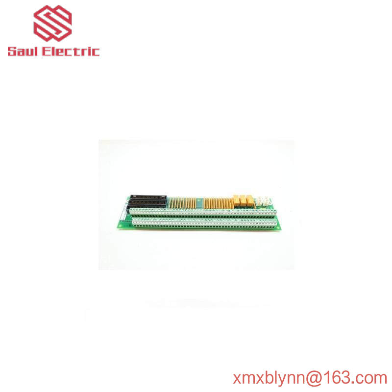
DS200DTBAG1AAA|Ge contact input terminal module
As mentioned above, the DS200DTBAG1AAA contact input terminal board was originally manufactured for General Electric’s Mark V family of turbine control systems. As you may know by its full name, the Mark V Series has specific applications in the management and control systems of automation components for wind, steam and gas turbines, and is considered a legacy series from GE, as its manufacturing has been discontinued within a few years of its initial release. While considerable as a legacy series, the DS200DTBAG1AAA product offers the Mark V family of turbine control systems, which is also one of the final products in the GE Mark family, using Speedtronic control system technology in the assembly of its various products. Although the DS200DTBAG1AAA printed circuit board itself can be defined as a contact input terminal board, it is not the product originally developed for this function; That would be missing three important product revisions of the DS200DTBAG1AAA device for the DS200DTBAG1 contact input terminal board.
Hardware tips and specifications
Given the specific intended functionality of this DS200DTBAG1AAA product, it is not surprising that this DS200DTBAG1AAA PCB utilizes its own set of capabilities to introduce hardware components and component specifications. The digital contact terminal board DS200DTBAG1AAA has two terminals and can connect up to 95 wires. The device also has five jumpers and two 2-pin connectors. Terminals connect signal cables to send and receive information used by drivers. There may be up to 190 wires connected to the GE digital contact terminal board DS200DTBAG1AAA, so you must be aware of possible damage to other components and boards. When connecting the DS200DTBAG1AAA model to other models in the Mark V DS200 series, four connections are used. Available connections are J12, JQR, JQS/T and JY; All of these connections have their own specific functions. For example, although JQS/T connections are provided on board, they are rarely used. The DS200DTBAG1AAA contact input terminal board is also assembled with several hardware jumpers that can be manually moved, although they all have the same general function. The DS200DTBAG1AAA PCB’s manual mobile hardware jumper is used to isolate the test contact output and is distinguished by its BJ1-BJ5 factory printed naming label. Before making any final purchase decision on this DS200DTBAG1AAA PCB, it must be recognized that the performance specifications and dimensions it was originally introduced have undoubtedly been changed, as it has a full history of triple revisions.
The DS200DTBAG1AAA Board’s original instruction manual material details a series of important instructions for safely and completely installing the product in its larger Mark V Series automatic drive assembly. The screwdriver is used to loosen terminals to remove wires, which means it could bump or scratch other components while unloading. To prevent this, use one hand to guide the screwdriver to the terminal you want to release. When removing the signal wires from the DS200DTBAG1AAA, try to move them to the side and away from the other boards. If possible, reinstall the signal cable before installing the replacement board to limit the chance of damaging the fragile board in the drive. If you can connect wires, hold the board only from the side and use both hands. Carefully place the board into the cabinet and align the holes with the holes in the rack where the board is to be mounted. When making a replacement, you must wear the wristband and attach the end of the wristband to an unpainted metal structure.

Frequently asked questions about DS200DTBAG1AAA
Does DS200DTBAG1AAA have a jumper?
Yes! The DS200DTBAG1AAA model is equipped with various jumpers, such as Berg jumpers. If the Berg jumper is removed, it isolates different parts of the DTBA model contact input to simplify troubleshooting of potential ground faults.
How do I get the manual that I will use with the DTBA model?
One of the most difficult things about having a DS200DTBAG1AAA model is the lack of manual usability. The reason the manual is so hard to find is that GE no longer makes the Mark V series. While the series no longer produces models, they are usually used, but do not come with manuals.
What is the voltage on the DS200DTBAG1AAA?
The voltage most often mentioned when using the DS200DTBAG1AAA model is 24 VDC. DTBA models in the Mark V series typically range from 24 to 125 VDC.
The DS200DTBAG1AAA model has multiple digital contact inputs; Which inputs are used for terminating?
In the digital contact input of the DS200DTBAG1AAA model, inputs 1 to 46 are usually used for terminating functions.
