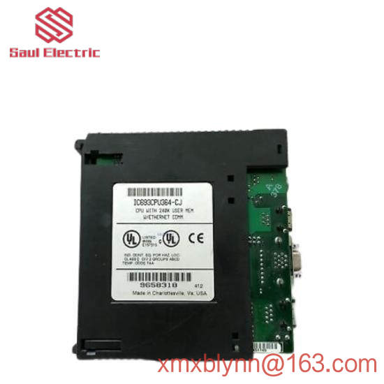
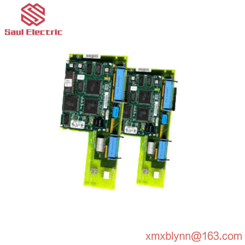
DS200DCFBG1BNC|The power board is manufactured by GE Industrial Control Systems for the Mark V turbine control system
The DS200DCFBG1BNC is a power board manufactured for General Electric’s Mark V Series replacement and optional boards. The DS200DCFBG1BNC circuit board is part of the Speedtronic Mark V control system, which has specific applications in the control and management systems of automatic drive components for wind, steam and gas turbines. The system control level power supply and enclosure fan are supplied by this card. The card is compatible with many GE branded exciters and drives and can be installed in a variety of systems. The board can be used by drives in the FC2000, AC2000, DC2000, ME2000 and CB2000 series. This larger Mark V series of DS200DCFBG1BNC printed circuit board, while having specific applications in relatively newly developed alternative energy components, must be considered a legacy product family that is now obsolete, as it was discontinued due to obsoletionin the years following the release of its initial product family. Indeed, this larger Mark V series of DS200DCFBG1BNC power boards is still a highly regarded GE product family, as it exists as one of the ultimate GE signature product families, integrating patented Speedtronic control system technology into its wide range of products. This DS200DCFBG1BNC printed circuit board, while itself definable as a power board, is not the original development of this particular Mark V Series feature; This will be the DS200DCFBG1 missing the three main product revisions of this DS200DCFBG1BNC PCB parent power board.
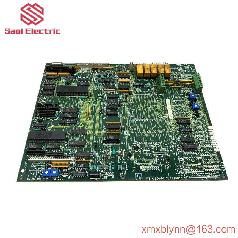
Hardware tips and specifications
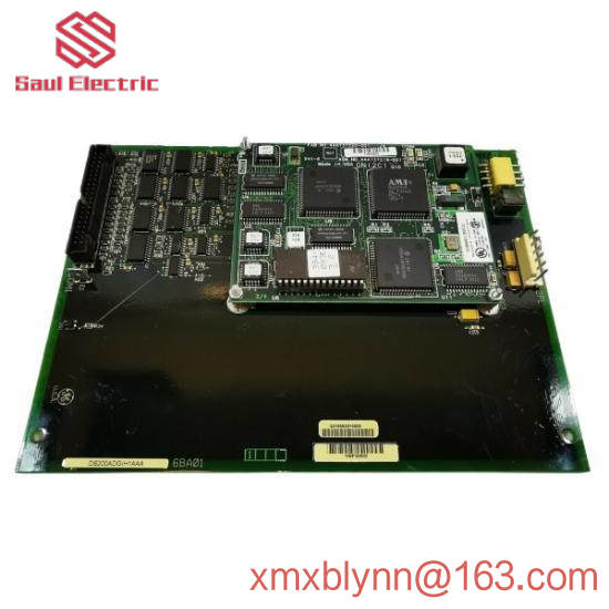
As with anything offered with GE’s Mark V family of turbine control systems; This DS200DCFBG1BNC printed circuit board is a product that offers uniqueness in many hardware component inclessions and specifications. The voltage fed to the board can be rated safely from 38 to 115 VAC. The DS200DCFBG1BNC consists of five circuits around the board. It includes a drive circuit, a control level power supply circuit, a motor excitation power supply circuit, and an AC and DC monitoring circuit. To ensure that the circuit is not interrupted, the three fuses on the board are protected. If any fuses need attention, integrated LED and neon indicators will alert the user. Monitoring voltage levels is important and can be done using one of the five test points on the card. You can use 12 jumpers and 7 DIP switches for user-led configuration. The unique voltage protection and suppression strategy of the DS200DCFBG1BNC Mark V series is mainly introduced into its larger Mark V Series by introducing a series of standardized hardware components through the DCFB abbreviated board; Including, but not limited to, various styles of capacitors, transistors, resistors, diodes, and integrated circuits. Five test points critical to the assembly of the DS200DCFBG1BNC product include:
P5 regulated power supply test point
DCOM test signals commonly refer to test points
P15 positive power supply test point
N15 negative power supply test point
ACCT Indicates the ACCT signal DCFB/SDCC test point
All of the above test points in the DS200DCFBG1BNC product assembly are named by combining their factory-printed naming labels and features (the DS200DCFBG1BNC PCB and its larger Mark V Series automatic driver assembly). The DS200DCFBG1BNC printed circuit board has a total of 12 configurable jumpers that can be used for custom purposes, although the DS200DCFBG1BNC power board uses 13, Because its higher revision history allows the JP13 Scaling Select for Shunt Jumper to be included in its internal components. The location of each Jumper in this product component, the factory printed naming label, and the specific DS200DCFBG1BNC board specific application are described in detail in the included DS200DCFBG1BNC Jumper Settings data sheet. If jumpers labeled JP13 or JP14 are present in the components of this DS200DCFBG1BNC product, it is safe to assume that they exist as harmless, functionally evading degenerate structures. Because these two jumpers are described in the manual material originally introduced by the DS200DCFBG1BNC PCB as a deleted jumper style. The installation parameters provided by the circuit board and driver should be met. Following these will ensure that the DS200DCFBG1BNC, as well as the drive, functions as expected. Illustrated instructions for wiring and mounting boards are provided in the equipment’s manual and data sheet. AX Control’s experienced and trusted sales team is happy to help you with all your DS200DCFBG1BNC needs. Prices and availability of all parts and repairs can be obtained by contacting our office by phone or email.
FAQ about DS200DCFBG1BNC
What circuits does the DS200DCFBG1BNC contain?
The DS200DCFBG1BNC has a circuit for a control-level power supply, the DS200DCFBG1BNC has a circuit for an electrical field power supply circuit and a driver circuit for an electrical field SCR gate pulse generator, and the DS200DCFBG1BNC has a circuit for monitoring multiple AC lines and DC motor signals.
What is the function of the VCO circuit on DS200DCFBG1BNC?
The VCO or voltage controller oscillator circuit on the DS200DCFBG1BNC converts the input voltage into a frequency signal.
How much voltage does DS200DCFBG1BNC get from CPT?
The DS200DCFBG1BNC obtains 38 VAC from the CPT or control power transformer.