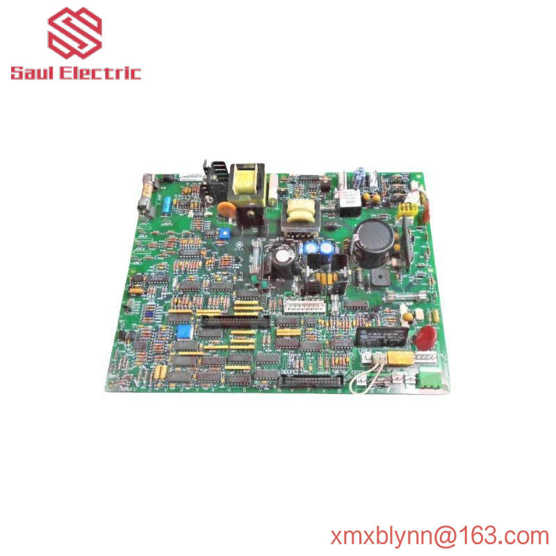
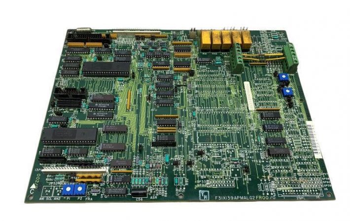
The DS200ITXDG1ABA board is labeled as a dynamic brake buffer board as part of the Mark V Series manufactured by General Electric. The DS200ITXDG1ABA product belongs to the Mark V family, one of the last in the GE Mark product family to feature Speedtronic control system technology, and exists as a legacy product family given that it was eventually discontinued many years after its initial release. The DS200ITXDG1ABA printed circuit board, or PCB for short, was not originally developed for its specific Mark V turbine control system family functional role; This is actually the DS200ITXDG1 female dynamic brake buffer board, conspicuously missing all three important product revisions of this DS200ITXDG1ABA PCB. The assembly of the DS200ITXDG1ABA PCB has been specially modified to adopt the Class A Major Function revision, Class B Minor Function revision, and Class A Artwork Configuration revision.
Hardware tips and specifications
The required operation of the IXTD board is provided through the circuit of the connected power/interface board (IMCP). When IMCP and IXTD boards are connected, they are connected via a four-pin connector. After the plate is installed, it will be mounted externally and must be resized to meet the worst-case switching requirements of dynamic braking IGBTs. The purpose of the buffer plate is to limit voltage transients at both ends of the IGBT and under all known operating conditions of the driver. Another function of the DS200ITXDG1ABA board is to adjust the output of the IGBT gate driver board so that it matches the electrical characteristics of the AT frame driver. AT frame drivers are available for variable and constant torque applications. The drive output current rating for variable torque applications is 500 ARMS.

DS200ITXDG1ABA board has three connector types; Bus I/O connectors, DBPL input connectors, and board pin connectors. All of these connector types have different pin numbers, nomenclature, and descriptions, which are detailed for convenience in the attached DS200ITXDG1ABA instruction manual. Bus I/O connectors and pin I/O connectors also have directions. Two pin examples related to pin I/O connectors are the E-6 and E-9 connectors, both of which are output connectors. The E-6 connector is the DB IGBT gate signal, and the E-9 connector is the connection of the external buffer resistor. A single plug-in connector that can be used to assemble this DS200ITXDG1ABA dynamic brake buffer plate is also fully discussed in the relevant General Electric instruction manual materials. The connector comes with a DBPL factory-printed naming label and connects the DS200ITXDG1ABA product to an accessible IMCP cousin printed circuit board product in the larger Mark V Series automatic drive assembly. For convenience, the plug-in connector positioning of the DS200ITXDG1ABA PCB is described separately in the available guide materials. Before making any single final purchase decision on this DS200ITXDG1ABA dynamic brake buffer, it is important to realize that the performance specifications and dimensions it was originally introduced to have undoubtedly changed as a result of its acceptance of a full triple revision history.
FAQ about DS200ITXDG1ABA
Is this DS200ITXDG1ABA PCB a fragile Mark V series product?
Yes. The substrate of this DS200ITXDG1ABA PCB is largely a bare component, which results in the fragile state of the DS200ITXDG1ABA PCB product.
Yes. Many IGBT modules from the Mark V series are supplied with our Mark V Series PCB products, although their warranty has been adjusted accordingly.
Do the components of this DS200ITXDG1ABA PCB have any factory drilled mounting holes?
The components of this DS200ITXDG1ABA PCB are drilled into multiple locations and are designed to aid in convenient and safe installation practices; Each hole is surrounded with insulation to comply with potentially damaging surface voltages.


Leave a comment
Your email address will not be published. Required fields are marked *