Call us 24/7+86 18030182217
GE DS200IMCPG1C: Precision Power Supply Interface for Industrial Controls

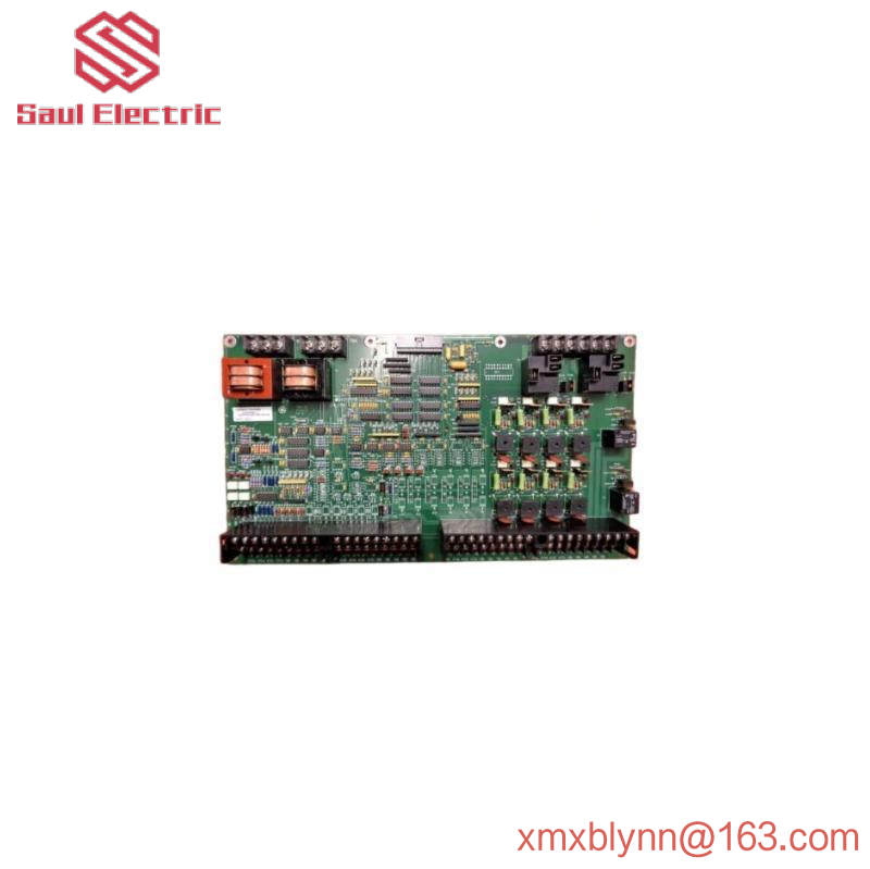
DS200ITXDG1ABA|Dynamic brake buffer plate

The DS200ITXDG1ABA board is labeled as a dynamic brake buffer board as part of the Mark V Series manufactured by General Electric. The DS200ITXDG1ABA product belongs to the Mark V family, one of the last in the GE Mark product family to feature Speedtronic control system technology, and exists as a legacy product family given that it was eventually discontinued many years after its initial release. The DS200ITXDG1ABA printed circuit board, or PCB for short, was not originally developed for its specific Mark V turbine control system family functional role; This is actually the DS200ITXDG1 female dynamic brake buffer board, conspicuously missing all three important product revisions of this DS200ITXDG1ABA PCB. The assembly of the DS200ITXDG1ABA PCB has been specially modified to adopt the Class A Major Function revision, Class B Minor Function revision, and Class A Artwork Configuration revision.

Hardware tips and specifications

The required operation of the IXTD board is provided through the circuit of the connected power/interface board (IMCP). When IMCP and IXTD boards are connected, they are connected via a four-pin connector. After the plate is installed, it will be mounted externally and must be resized to meet the worst-case switching requirements of dynamic braking IGBTs. The purpose of the buffer plate is to limit voltage transients at both ends of the IGBT and under all known operating conditions of the driver. Another function of the DS200ITXDG1ABA board is to adjust the output of the IGBT gate driver board so that it matches the electrical characteristics of the AT frame driver. AT frame drivers are available for variable and constant torque applications. The drive output current rating for variable torque applications is 500 ARMS.
GE DS200IMCPG1C: Precision Power Supply Interface for Industrial Controls

DS200ITXDG1ABA board has three connector types; Bus I/O connectors, DBPL input connectors, and board pin connectors. All of these connector types have different pin numbers, nomenclature, and descriptions, which are detailed for convenience in the attached DS200ITXDG1ABA instruction manual. Bus I/O connectors and pin I/O connectors also have directions. Two pin examples related to pin I/O connectors are the E-6 and E-9 connectors, both of which are output connectors. The E-6 connector is the DB IGBT gate signal, and the E-9 connector is the connection of the external buffer resistor. A single plug-in connector that can be used to assemble this DS200ITXDG1ABA dynamic brake buffer plate is also fully discussed in the relevant General Electric instruction manual materials. The connector comes with a DBPL factory-printed naming label and connects the DS200ITXDG1ABA product to an accessible IMCP cousin printed circuit board product in the larger Mark V Series automatic drive assembly. For convenience, the plug-in connector positioning of the DS200ITXDG1ABA PCB is described separately in the available guide materials. Before making any single final purchase decision on this DS200ITXDG1ABA dynamic brake buffer, it is important to realize that the performance specifications and dimensions it was originally introduced to have undoubtedly changed as a result of its acceptance of a full triple revision history.

FAQ about DS200ITXDG1ABA
Is this DS200ITXDG1ABA PCB a fragile Mark V series product?

Yes. The substrate of this DS200ITXDG1ABA PCB is largely a bare component, which results in the fragile state of the DS200ITXDG1ABA PCB product.

Yes. Many IGBT modules from the Mark V series are supplied with our Mark V Series PCB products, although their warranty has been adjusted accordingly.
Do the components of this DS200ITXDG1ABA PCB have any factory drilled mounting holes?

The components of this DS200ITXDG1ABA PCB are drilled into multiple locations and are designed to aid in convenient and safe installation practices; Each hole is surrounded with insulation to comply with potentially damaging surface voltages.

General Electric DS200IQXSG1AAA Inverter Snubber Board for Mark V Turbine Control System

DS200IQXSG1AAA|Inverter buffer plate

As shown in the short product description inserted above, the DS200IQXSG1AAA printed circuit board product offered by GE was originally manufactured as a specific function placement for the inverter buffer board in its larger Mark V turbine control system family of automatic drive components. As you will most likely be able to infer from its full extended series name, the Mark V series to which this DS200IQXSG1AAA board belongs has specific applications in compatible and popular systems for the management and control of automatic drive components for wind, steam and gas turbines. Given the possible alternative energy applications for the Mark V series of this DS200IQXSG1AAA PCB, it must still be considered to exist as a legacy series for GE, as production ceased in the years after its original Mark product line was established due to the obsolesce of the retailer identification function series. Although the Mark V series of the DS200IQXSG1AAA PCB is outdated as a whole, it is still the Mark product family in high demand in the general automation industrial market, because it is one of the last GE Mark product families to be developed. Utilizing the patented Speedtronic control system technology, which was first introduced with the launch of the previous Mark I series.
General Electric DS200IQXSG1AAA Inverter Snubber Board for Mark V Turbine Control System

Hardware tips and specifications

As with any printed circuit board product offered in our extended new and refurbished stock here, the intended Mark V Series functionality of this DS200IQXSG1AAA PCB acts to accept a specific family of hardware components along with its normal Mark V Series components. The GE Inverter buffer board DS200IQXSG1AAA has 8 terminal connectors. The terminals are labeled E1 to E8. The GE inverter buffer board DS200IQXSG1AAA also contains an 8-pin connector and a film capacitor mounted on the board. The board is one of several boards installed in the board cabinet. The dimensions are 6.25 x 5 inches and the four holes in the corners are aligned with the matching mounting holes on the board frame. If no new screws are available, use the same screws that secured the old plate. Given that this DS200IQXSG1AAA PCB belongs to the Mark V legacy family of turbine control systems, it is not surprising to find that the instruction manual material for which it was originally produced is largely unavailable online. In view of this, the DS200IQXSG1AAA functional product number itself can be used as the primary source of hardware component and component specification information for the DS200IQXSG1AAA Board; Various DS200IQXSG1AAA Board details are encoded in a series of successive functional naming segments. For example, the DS200IQXSG1AAA functional product number begins with the inclusion of a dual-function DS200 segment that categorizes the normal Mark V Series assembly version of this DS200IQXSG1AAA PCB and its original manufacturing location. Some other related hardware details revealed through the DS200IQXSG1AAA board’s functional product number include:

IQXS Functional Products acronym
The first group of Mark V series products
Common PCB coating style
Grade A main function renovation
Grade A secondary functional overhaul
Class A Artwork Configuration revision
Because the circuit board and moving parts in the driver generate heat, cooling is an important consideration when installing the driver. The drive must have a clean air source that can flow freely through the drive to keep the components within the permitted temperature range. The drive is designed so that cool, clean air enters the drive from the bottom and rises through the inside of the drive. It goes around and over components and draws heat from the drive. Another consideration is that the drive is not near other devices that generate heat, and the walls around the drive are not heated by devices on the other side of the wall. If the drive becomes overheated and out of the temperature range, overheating will be detected and the drive will automatically stop. This safety feature will prevent damage to the components. It can also prevent the development of fire hazards. Typically, the voltage suppression and limiting strategy of this DS200IQXSG1AAA PCB involves incorporating the standardized hardware component selection of the Mark V Series into its normal Mark V Series components; Includes various styles of capacitors, resistors, transistors, diodes and integrated circuits.

GE DS200IIBDG1A AC2000I IGBT Driver Card

DS200IIBDG1A|IGBT gate driver board

This DS200IIBDG1A GE printed circuit board can indeed be better defined through its official functional product description as an IGBT gate driver board, as it appears in the original Mark V Turbine Control System series instruction manual material. As you might tell from its full name, the Mark V series to which this DS200IIBDG1A printed circuit board, or PCB for short, belongs has specific applications in the management and control systems of automated drive components for wind, steam and gas turbines. The Mark V Series is a legacy series as it has been discontinued for many years since its original release by GE manufacturers and exists as one of GE’s final product families, incorporating patented Speedtronic control system technology in its various products. The DS200IIBDG1A PCB edits the original DS200IIBDG1 IGBT gate driver board by including A single Class A functional product revision.

Hardware tips and specifications

This DS200IIBDG1A printed circuit board product utilizes a set of specific and critical hardware specifications and component inclusions to obtain the functional status of the IGBT gate driver board. The GE insulated gate bipolar transistor (IGBT) board DS200IIBDG1A contains nine LED indicators to provide the status of the board processing. The LED is visible from the inside of the circuit board cabinet and appears red when lit. When the board is energized and the driver is running, the LED indicates the operation of the board. Since leds are only visible when the board is powered on, great care must be taken when opening the cabinet. When viewing the LED, do not touch any of the components in the drive, and be sure not to drop any metal, dirt, or other debris into the large Mark V Series Autopilot drive on the DS200IIBDG1A PCB. Before making A final purchase decision on this DS200IIBDG1A IGBT gate driver board, it is critical to recognize that the Class A functional product revision of this DS200IIBDG1A PCB will almost certainly change the performance specifications and dimensions of this DS200IIBDG1A product. Change it from its original state of basic revision. The functions and applications of each specific LED in this DS200IIBDG1A PCB assembly are described in detail in the DS200IIBDG1A instruction manual material embedded in the manual TAB above.
GE DS200IIBDG1A AC2000I IGBT Driver Card

The GE insulated gate bipolar transistor (IGBT) board DS200IIBDG1A has multiple connectors, and when installing the replacement board, you must ensure that the cable is connected to the exact same connector. To ensure that they are reconnected to the same connector, check the defective circuit board and note the connector identifier indicating the connector to which the cable has been connected. Labels are then made and attached to the cable to show where the cable is connected on the new board. In addition, the board contains one or more jumpers that configure the board to handle the drive’s information in a particular way. Other jumpers are set in the factory and are used in the factory for testing purposes only. The original factory print information that comes with the DS200IIBDG1A board identifies the jumper and describes the jumper Settings and how they change the board behavior. This particular DS200IIBDG1A product is filled with a total of manually removable hardware jumpers; The jumper is a Berg type jumper isolated on a DS200iIBDG1a-based board by J1 factory printed nomenclature. This jumper is factory set, so it should not be accessed or customized during the specification function of the DS200IIBDG1A board, although it does make a selection for specific gate on-delay for this DS200IIBDG1A device.

Frequently asked questions about DS200IIBDG1A
What is the purpose of this Class A functional revision of the DS200IIBDG1A IGBT gate driver board?

This Class A product revision of the DS200IIBDG1A PCB is classified as a functional product revision because it represents a significant improvement to the general performance specifications and overall functionality of the DS200IIBDG1A board without sacrificing any durability or aesthetic qualities.
What type of components does this DS200IIBDG1A IGBT gate driver card have?

The DS200IIBDG1A IGBT gate driver card features common Mark V Series components, as indicated on the DS200 Series label in the DS200IIBDG1A functional product number.

GE DS200DTBAG1AAA: Advanced Digital Input/Output Module for Mark V Systems

DS200DTBAG1AAA|Ge contact input terminal module

As mentioned above, the DS200DTBAG1AAA contact input terminal board was originally manufactured for General Electric’s Mark V family of turbine control systems. As you may know by its full name, the Mark V Series has specific applications in the management and control systems of automation components for wind, steam and gas turbines, and is considered a legacy series from GE, as its manufacturing has been discontinued within a few years of its initial release. While considerable as a legacy series, the DS200DTBAG1AAA product offers the Mark V family of turbine control systems, which is also one of the final products in the GE Mark family, using Speedtronic control system technology in the assembly of its various products. Although the DS200DTBAG1AAA printed circuit board itself can be defined as a contact input terminal board, it is not the product originally developed for this function; That would be missing three important product revisions of the DS200DTBAG1AAA device for the DS200DTBAG1 contact input terminal board.

Hardware tips and specifications

Given the specific intended functionality of this DS200DTBAG1AAA product, it is not surprising that this DS200DTBAG1AAA PCB utilizes its own set of capabilities to introduce hardware components and component specifications. The digital contact terminal board DS200DTBAG1AAA has two terminals and can connect up to 95 wires. The device also has five jumpers and two 2-pin connectors. Terminals connect signal cables to send and receive information used by drivers. There may be up to 190 wires connected to the GE digital contact terminal board DS200DTBAG1AAA, so you must be aware of possible damage to other components and boards. When connecting the DS200DTBAG1AAA model to other models in the Mark V DS200 series, four connections are used. Available connections are J12, JQR, JQS/T and JY; All of these connections have their own specific functions. For example, although JQS/T connections are provided on board, they are rarely used. The DS200DTBAG1AAA contact input terminal board is also assembled with several hardware jumpers that can be manually moved, although they all have the same general function. The DS200DTBAG1AAA PCB’s manual mobile hardware jumper is used to isolate the test contact output and is distinguished by its BJ1-BJ5 factory printed naming label. Before making any final purchase decision on this DS200DTBAG1AAA PCB, it must be recognized that the performance specifications and dimensions it was originally introduced have undoubtedly been changed, as it has a full history of triple revisions.

The DS200DTBAG1AAA Board’s original instruction manual material details a series of important instructions for safely and completely installing the product in its larger Mark V Series automatic drive assembly. The screwdriver is used to loosen terminals to remove wires, which means it could bump or scratch other components while unloading. To prevent this, use one hand to guide the screwdriver to the terminal you want to release. When removing the signal wires from the DS200DTBAG1AAA, try to move them to the side and away from the other boards. If possible, reinstall the signal cable before installing the replacement board to limit the chance of damaging the fragile board in the drive. If you can connect wires, hold the board only from the side and use both hands. Carefully place the board into the cabinet and align the holes with the holes in the rack where the board is to be mounted. When making a replacement, you must wear the wristband and attach the end of the wristband to an unpainted metal structure.
GE DS200DTBAG1AAA: Advanced Digital Input/Output Module for Mark V Systems

Frequently asked questions about DS200DTBAG1AAA
Does DS200DTBAG1AAA have a jumper?

Yes! The DS200DTBAG1AAA model is equipped with various jumpers, such as Berg jumpers. If the Berg jumper is removed, it isolates different parts of the DTBA model contact input to simplify troubleshooting of potential ground faults.
How do I get the manual that I will use with the DTBA model?

One of the most difficult things about having a DS200DTBAG1AAA model is the lack of manual usability. The reason the manual is so hard to find is that GE no longer makes the Mark V series. While the series no longer produces models, they are usually used, but do not come with manuals.
What is the voltage on the DS200DTBAG1AAA?
The voltage most often mentioned when using the DS200DTBAG1AAA model is 24 VDC. DTBA models in the Mark V series typically range from 24 to 125 VDC.
The DS200DTBAG1AAA model has multiple digital contact inputs; Which inputs are used for terminating?

In the digital contact input of the DS200DTBAG1AAA model, inputs 1 to 46 are usually used for terminating functions.

GE DS200DSPCH1ADA High-Performance Digital Signal Processor Module

DS200DSPCH1ADA|Digital signal processor control board

The DS200DSPCH1ADA is a GE digital signal processor control board compatible with GE’s Mark V Speedtronic control systems for steam and gas industrial turbines. The DS200DSPCH1ADA provides communication bandwidth and processing power for direct control of the system’s power converter applications and high-performance drivers. The board has expandable inputs and outputs. The larger Mark V turbine control system family that the DS200DSPCH1ADA device belongs to is considered a legacy product family that is now obsolete, as it was eventually discontinued many years after its initial release. Given this, it can also be defined as one of GE’s final product lines to take advantage of the brand’s patented Speedtronic control system technology, which was first offered in the late 1960s along with the original version of the Mark V series. This DS200DSPCH1ADA PCB is not the original product of its intended Mark V series features; This will be missing the DS200DSPCH1ADA product with three important product revisions to the DS200DSPCH1 motherboard.

Hardware tips and specifications

The DS200DSPCH1ADA is a complex circuit board with multiple subboards. Given the presence of this DS200DSPCH1ADA product, its DS200DSPCH1ADA functional product number does not mention the special Mark V series assembly version, which is somewhat unusual, as is the case with other typical Mark V Series motherboards. One board is mounted parallel to the board surface using a bracket and the other board is mounted vertically. One of the subboards is used to provide scaling, buffering, isolation, and conditioning of the signals so that they can be accessed and used by the DS200DSPCH1ADA digital signal processor. The DS200DSPCH1ADA has two backplane connectors on the back edge. The board is built from an additional front panel with multiple I/O and LED indicators. The panel also has a reset button and two setting screws (top and bottom) that help lock the board in place when mounting it into the rack system. When replacing the board, make sure to disconnect all power from the driver first. An incorrect installation program may result in personal injury. Each LED indicator in this DS200DSPCH1ADA printed circuit Board product assembly has been affixed to their own factory-printed naming label, which references the DS200DSPCH1ADA instruction manual attached above for identification. Some specific LED indicators that are important for the functional fault diagnosis capability of this DS200DSPCH1ADA board include:

Green IMOK universal board function indicator
Red FAIL VME bus fault fault condition indicator
Amber LED1 indicator light
Amber LED2 indicator
Amber LED3 indicator
Amber LED4 indicator
GE DS200DSPCH1ADA High-Performance Digital Signal Processor Module
While the above green and red LED indicators are named after their factory-printed naming labels and general Mark V Series automatic driver assembly applications, the above four amber indicators do not appear to have made a similar effort, as GE describes these leds as available through software options to define its individual projects. AX Control has a large existing stock of Speedtronic boards and other components, so we can fill your order quickly. Most stock orders will be shipped the same day you place your order. If you need expedited shipping or have any other special requirements, please let us know. Our company uses a variety of transportation methods to ship from our North Carolina facility to locations around the world.

FAQ about DS200DSPCH1ADA
Why are only the first two significant revisions of this DS200DSPCH1ADA product considered backward compatible?

Only the first two versions of the DS200DSPCH1ADA PCB can be considered backward compatible, as they both exist as functional styles for the Mark V Series product versions.
What type of PCB protective coating does the DS200DSPCH1ADA device achieve?

The base board of this DS200DSPCH1ADA PCB is protected by a thin, chemically coated conformally coated PCB coating.

GE DS200DPCBG1AAA - High-Performance Digital Signal Processor Module

DS200DPCBG1AAA|Mark V Series turbine control system

This DS200DPCBG1AAA printed circuit board, or PCB for short, was originally manufactured to be placed in the Mark V turbine control system family of respected automated industrial retailer General Electric. As you will no doubt have seen from the full extended series names provided above, the DS200DPCBG1AAA product belongs to the Mark V series, which has specific applications in popular wind power, steam control and management systems, and has turbine automatic drive components, and is considered a legacy series from General Electric. Because it was eventually discontinued a few years after its initial release. The larger Mark V series of his DS200DPCBG1AAA PCBS, while a legacy family at GE, also exists as one of GE’s last product lines to take advantage of the company’s patented Speedtronic control system technology. This DS200DPCBG1AAA printed circuit board can indeed be better defined as the IOS + Power Connect board; Although the Mark V series product originally developed with this feature was the DS200DPCBG1 mother printed circuit board.

Hardware tips and specifications

As with any GE Mark V turbine control system family, the DS200DPCBG1AAA PCB utilizes its own set of features – introducing hardware components and component specifications. The GE IOS + Power Connect Board DS200DPCBG1AAA has two wire terminals and can connect up to six signal cables. The GE IOS + Power Connect Board DS200DPCBG1AAA also has a fuse and a toggle switch. The fuse DS200DPCBG1AAA on the GE IOS + Power Connect Board protects the board from damage when too much current is applied to the board, even if the power surge is brief. When a fuse is blown, you can visually inspect the fuse, and if the components within the fuse are intact, the fuse is still running. If the component is damaged or lost, the fuse is blown and must be replaced. Have a fuse on hand with the same rating as the fuse on the circuit board. You can refer to the written documentation to obtain the fuse rating, or if the rating is printed on the fuse, the rating can be obtained. However, if the ratings are not exactly the same, you may damage the board by exposing it to currents that could damage the board. Before disconnecting the power to the drive, you must communicate with others working around the drive that you plan to take the drive offline, and that their productivity may suffer. Consult someone who knows about drive installation to find out how to power it. The large automation driver of the DS200DPCBG1AAA PCB will have a power supply associated with it, which you can turn off or remove the fuse from.
GE DS200DPCBG1AAA - High-Performance Digital Signal Processor Module

While the specific fuse information for this DS200DPCBG1AAA product certainly warrants attention, its previous placement on this personalized product page has more to do with the general lack of related instruction manual material on the Internet for this DS200DPCBG1AAA PCB. It is not related to the importance of the DS200DPCBG1AAA product fuse. That being said, the DS200DPCBG1AAA functional product number will present itself as the primary source of hardware component and component specification information for the DS200DPCBG1AAA board. The DS200DPCBG1AAA Feature Product number begins with the DS200 Series label, which holds dual and describes the domestic location of the normal Mark V Series components of the DS200DPCBG1AAA board and their original manufacturing location. Some of the other relevant DS200DPCBG1AAA Board hardware details revealed in the function block of the DS200DPCBG1AAA product number include the DPCB function abbreviation for this DS200DPCBG1AAA PCB, the normal PCB coating style, And a complete triple revision history at the end.

FAQ about DS200DPCBG1AAA
What does this DS200DPCBG1AAA IOS + Power Connect Board’s normal PCB coating style require?

The normal PCB coating present in this DS200DPCBG1AAA PCB assembly is a thick layer of basic chemical application daily wear protection that wraps and protects individual DS200DPCBG1AAA hardware components according to their functional priority.

GE DS200DMCBG1AKG IOS DUP Processor Board for Industrial Automation Systems

DS200DMCBG1AKG|IOS DUP processor board

The DS200DMCBG1AKG is a GE IOS processor board produced by trusted industrial retailer General Electric. The relative scarcity of instruction manual materials on the Internet makes it a difficult product to isolate specific manufacturers and families, but at AX Control we do everything possible to keep this module in stock to meet your various automation industrial needs. This particular PCB is modified by functional revision 1 of A, functional revision 2 of K, and art revision rated G. As mentioned earlier, this DS200DMCBG1AKG General Electric product was manufactured for their Mark V family of turbine control systems. As you might tell from its full extended series name, this DS200DMCBG1AKG PCB’s Big Mark V Series has specific applications in popular and compatible management and control systems for automated drive components for wind, steam and gas turbines. The Mark V series of this DS200DMCBG1AKG PCB is considered to be a traditional product range at GE, as it has been discontinued for many years after its original establishment. Indeed, the Mark V turbine control system family is still well updated, as it was one of GE’s last product families to incorporate patented Speedtronic control system technology into its various products.

Hardware tips and specifications

Like many GE Industrial Systems Fanuc products, the GE IOS DUP processor board DS200DMCBG1AKG is unique in a number of important hardware specifications. Based on a thorough visual inspection, the DMCB model contains several unique elements, including:

Three 26-pin connectors
A 40 pin connector
2 LED indicators in total
Surface mount RESET switch
19 jumpers in total
The installer can use the jumper on the DS200DMCBG1AKG to change the behavior of the board. The manual that came with the factory original board describes the jumpers and how they change the behavior of the board, although as mentioned earlier, the online availability of this manual is relatively limited. While customizable hardware jumpers do exist on the backboard of this DS200 DMCB, not all of them can be moved by installers or qualified service providers. Some of the jumpers on the baseboard of this module are hardwired jumpers and are only used for testing purposes in manufacturing plants. These jumpers can also be identified by the GE Fanuc or other series manuals that came with the original board. While manual information for this model is often lacking on the Internet, a series of factory-issued labels on the backboard of this board can clarify other important hardware specifications. For example, the DS200DMCBG1AKG model has the “IOS Master” function description posted at the top of the board. In addition to this initial General descriptive label, this DMCG PCB model is equipped with a variety of labels, including C-ESS, V 5, and General Electric U.S.A, as well as standard industry labels for hundreds of relays and numerous plugs on the DMCG surface. This DS200DMCBG1AKG model appears to have a total of nine plugs on the backboard of this PCB.

Installation tips and specifications

While the DS200DMCBG1AKG offers a range of important hardware specifications, it is also important to introduce a careful and sensible installation process. Note that when you replace this DMCB board, you simply move the jumper to match the position of the jumper on the old board. When you inspect the board side by side, you may find that the jumpers on the replacement board are in different locations due to a design update. The best practice is to identify jumpers on an old board by the identifier printed on the board. The identifier of the jumper may be JP1, JP2, or JP3. Leds are identified as CR2 and CR12. During installation, it is important to find the correct jumper on the replacement board and make sure it covers the same pins.

The installation of the DS200DMCBG1AKG module is supported by the inclusion of several factory holes and insulation holes in the substrate. Safe PCB installation should also be encouraged by a common printed circuit board protection coating for this processor board, which is rated much thicker than the alternative conformal PCB coating. As mentioned earlier, this particular DMCB product has a relatively extensive history of triple revisions; Feature Revision 1 is rated A, Feature Revision 2 Special is rated K, and Artwork Revision is rated G. These revisions can significantly improve the overall drive function and can dramatically change the size of the module components. With this in mind, it is always important to ensure correct module revisions before purchasing a DS200DMCBG1AKG. Even if the component is in a different position on the baseplate compared to the replacement module; When properly installed, the replacement board provides the same processing capabilities. This should be achieved by performing a series of voltage protection tests on the replacement board to ensure that it maintains compatibility.
GE DS200DMCBG1AKG IOS DUP Processor Board for Industrial Automation Systems

FAQ about DS200DMCBG1AKG
What are the plug labels for this DS200DMCBG1AKG product?

While the DS200DMCBG1AKG offers some jumpers and other components with standard labels, it offers a range of plugs labeled 1PL through 4PL. A plug label specific to this PCB component is present in its ARCPL plug and corresponding label.
Does the DS200DMCBG1AKB component itself have any printed labels?

Yes. Although the printed circuit board itself is printed with many labels for identification purposes, many relays and circuits have printed information indicating the characteristics of the product; Includes Toshiba TC551001BPL-85 components.
Does the DS200DMCBG1AKG come with any capacitors?

Yes. The DS200DMCBG1AKG DOS DUP processor board uses multiple capacitors for voltage protection. Many of these capacitors are located in the upper left quadrant of the PCB assembly; Easily recognized by its distinctive bright blue color.

GE DS200DMCBG1AED - High-Performance Industrial Control Board

DS200DMCBG1AED|DOS DUP processor board

Ge’s DS200DMCBG1AED printed circuit board product was originally designed and manufactured for the Mark V family of turbine control systems, as described in its initial release of guidance manual materials. These instructional materials can be a bit difficult to access online, as they are overshadowed by the traditional status of the Mark V series, which was eventually encouraged by the discontinuation that occurred within a year of its original Mark series release. The larger Mark V series of this DS200DMCBG1AED PCB, as indicated by the full extended series name attached above, has a range of applications in the control and management systems of popular and compatible wind, steam and gas turbine automation drive components and is considered a highly anticipated product family in the general automation industrial market. Because it exists as one of the last GE Mark product families to be developed, the patented Speedtronic control system technology is integrated into a range of devices. The Speedtronic control system technology used in the Mark V series of this DS200DMCBG1AED PCB was originally introduced with the release of the Mark I series in the late 1960s.

Hardware tips and specifications

The GE DOS DUP processor board DS200DMCBG1AED contains three 26-pin connectors, one 40-pin connector, and 19 jumpers. The board also has 2 leds. The GE DOS DUP processor board DS200DMCBG1AED also has two fuses to provide overvoltage protection. If there is an instantaneous surge in the circuit board’s power supply, the components in the fuse will blow and the circuit board will stop working completely, or stop working in the circuit protected by the fuse. If the fuse is rated incorrectly, the components on the circuit board will be damaged. Therefore, if you replace a fuse, only use a replacement of the same rating. Information about fuses is provided in the information that comes with the original circuit board when you leave the factory. Alternatively, you may find a rating printed on the fuse. Typically, fuses for such DS200DMCBG1AED PCBS are considered part of a larger voltage protection strategy involving various styles of Mark V Series standardized voltage limiting hardware components, including but not limited to various styles of Mark V Series transistors, resistors, diodes, etc. Finally, the recognizable blue drum electrolytic capacitor. This DS200DMCBG1AED PCB is not an original development of its specific Mark V Series functionality; These are actually three important product versions of the DS200DMCBG1, the parent of the DOS DUP processor board, which does not use this DS200DMCBG1AED PCB. Although this DS200DMCBG1AED product is considered to belong to the first group of products in the Mark V turbine control System family, the true meaning of this classification must be described as unknown given the lack of dedicated online instruction manual materials related to this DS200DMCBG1AED board due to its functional full family obsolete.
GE DS200DMCBG1AED - High-Performance Industrial Control Board

Checking the condition of the fuse is a quick initial step to troubleshooting the board, as it only requires a visual inspection. If you suspect that the board is not operating as expected, you can open the board door and locate the fuse on the board. If one or both fuses blow, disconnect all power to the drive, remove the circuit board, and replace the fuse. Restart the drive and determine if the board is up and running again. If the problem persists, the next step is to look at the 2 leds on the board. Leds are identified as CR2 and CR12 on the circuit board and are red when lit. Given that this DS200DMCBG1AED PCB belongs to the now obsolete Mark V Turbine Control System Legacy series, it is not surprising to find that a large number of the original printed instruction manual materials on the Web do not consider it. Therefore, the DS200DMCBG1AED functional product number itself can be regarded as the main source of information about the DS200DMCBG1AED board; Encode various details in a series of continuous functional naming segments. For example, the DS200DMCBG1AED functional product number begins with a dual-function DS200 series label, which entrusting the normal Mark V series component of the DS200DMCBG1AED PCB and its domestic original manufacturing location. Some other related hardware details revealed through the PCB’s DS200DMCBG1AED feature product number include:

DMCB Functional Products Acronym
The first group of Mark V series products
Three fold revision table
Frequently asked questions about DS200DMCBG1AED
Are the three important product versions of the DS200DMCBG1AED PCB considered backward compatible?

Nooooo. Only the first two versions of this DS200DMCBG1AED PCB can be considered backward compatible as they exist as functional styles matching the Mark V Series product version.
Where exactly is this DS200DMCBG1AED board made?

This DS200DMCBG1AED PCB is manufactured at GE’s factory site in Salem, Virginia.

General Electric DS200DDTBG2ABB, I/O Terminal Board for Mark V Series

DS200DDTBG1A|LCI auxiliary I/O terminal board

Where does the power supply for DS200DDTBG1A board come from?

The power supply of the DS200DDTBG1A board is provided by the connected ADMA board.
The DS200DDTBG1A board has high voltage AC input, high current signal input, low current signal input, and 4-20 mA current loop input, but also has non-dedicated voltage input. What is a non-private voltage input?

A non-dedicated voltage input is an input provided via a differential input voltage amplifier that feeds an analog VCO input to the ADMA board. These inputs are composed of screw terminals and are protected from voltage surges.
There are 12 jumpers on DS200DDTBG1A board. What are these jumpers used for?

The purpose of the jumper is to redistribute the LEM and CT input channels so that they become inputs to the 4-20 mA current loop signal.
There are four voltage outputs on the DS200DDTBG1A board, what are these outputs and what is their composition?

The four voltage outputs on the DDTB board are buffered analog outputs, available via screw terminals. Each output has a 200 ohm series resistor that allows the amplifier to be isolated from the customer connection. The buffer output includes a gain 2 that provides a ±10 V output range of ±5 V from the connected ADMA board.
About DS200DDTBG1A
The DS200DDTBG1A model is called the Auxiliary input/Output Terminal Board, and information about it can be found on page 20 of the GEH-6373 series manual. This model is best used as a terminal board for all auxiliary inputs and outputs. There is a part manual labeled GEH-100219, which details functions, general characteristics, application data, and warranty and replacement information.

In the DS200DDTBG1A model, there is an add-only electronic ID memory feature that contains all board identification and hardware version information. To access this memory, one must go through a 1-wire LAN, which allows the connected DSPC board to identify the circuit board present in the system.

The DS200DDTBG1A model is equipped with a 4-20 mA current loop input that allows LEM or CT input channels to be reassigned within the model, and certain jumpers must be reset to perform this function. This model is also equipped with 33 test points that can be used for signal measurement. The model has a total of 17 leds, one LED on this board is used to indicate the status of the DS200DDTBG1A board, while the other 15 are driven by software and hardware.

GE IC693MDL730 Output Module: Advanced Control for Industrial Automation

IC693MDL730|12/24 VDC positive logic output module

Brand GE Fanuc
Series Series 90-30
Manufacturer GE Fanuc
Part number IC693MDL730
Series Series 90-30
The life cycle status is positive
Part number IC693MDL730
Power Supply Type DC
Product description Discrete output module
Output power voltage 12 to 24 VDC
Number of channels eight (8), single group
GE IC693MDL730E: 2-Amp Output Module, Precision Control Solutions

The IC693MDL730 is a positive logic output module in the GE Fanuc 90-30 series Programmable Logic controller (PLC) product family, now part of Emerson Automation. The module has eight (8) discrete output channels in a single set, providing an output voltage range of 12-24 VDC with a ripple of +20%, -15%. Each channel provides an output current of 2 amps per point; 60 amps per fuse at 2 ° C; 50 amps per fuse at 4 degrees Celsius. The IC693MDL730 has a 1500 V isolation between the magnetic field side and the logical side. The output channel has a surge current rating of 9.4 amps for 10 milliseconds; The maximum output voltage drop is 12 volts; The maximum off state leakage current is 1 mA, and the typical on and off response time for each transition is 2ms. The module occupies a single slot on a 90-30 backplane and is compatible with any I/O slot on a 90-30 series five (5) or ten (10) backplane. When all outputs are energized, its current consumption is 55 mA, coming from the 5 VDC bus on the backplane. The IC693MDL730 is compatible with a wide range of electrical loads, especially motor starters, solenids and indicators. An external power supply must be connected to the module to provide operating power. The status LED indicator is installed on the front panel of the module and includes a fuse indicator, a module failure indicator, and eight (8) channel indicators assigned to each output channel that describe the operating status of each output point. The module comes with a removable terminal board to simplify maintenance.

The IC693MDL730 PLC module has a 12 to 24 volt DC voltage rating with positive logic and 2 amp output current. The component has a DC power supply and comes with 8 points. The device has a load current of 2 amps per point, while response times are rated at 2 ms ON and 2 ms OFF. The output type is transistor output, and the module has positive polarity. The connector type is the terminal box with 20 screws that comes with the module.

Search for products

Back to Top
Product has been added to your cart